Square tiling
The square tiling, square grid, square tessellation or square lattice (Schläfli symbol {4,4}) is one of three possible regular tilings of the plane, alongside the hexagonal tiling and triangular tiling. It is constructed with four squares being placed at each vertex.
The square tiling is the most familiar of all 2D tilings, with cell positions being easily and uniquely defined via Cartesian coordinates, and is the grid on which cellular automata are simulated most frequently.
Coordinates, directions and displacements
Cartesian coordinate system
The square tiling can be very easily described with Cartesian coordinates, as any combination of two integers will correspond to a unique grid cell.
Notating displacement
Cartesian coordinates allow for the very easy definition of directions and displacements of moving objects; one need only consider said object's displacement in the x direction and its displacement in the y direction in order to notate its overall displacement. As such, displacement can be notated as
where:
- x is the object's displacement in the x-direction (usually greater than y)
- y is the object's displacement in the x-direction (usually lesser than x)
With the exception of orthogonal and diagonal displacements, which are detailed in a dedicated section below, any given displacement (referred to here as an "asymmetric displacement") can be said to be a member of a group of eight similar displacements, in which any member can be converted to any other member through a satisfactory composition of mirror reflections and 90-degree rotations.
| (x,y) | (x,-y) | (-x,y) | (-x,-y) |
| (y,x) | (y,-x) | (-y,x) | (-y,-x) |
Reversing the positions of x and y can be considered reflection across a diagonal line, whereas reversing the sign of x or y can be considered reflection across an orthogonal line (alternatively, a reverse in direction; if positive x means towards the right, negative x equivalently means that same value of x but to the left).
Displacement notation can also be used to notate directions in general, in which case both numbers are usually positive and in descending order.
Notating velocity
For periodic moving objects such as spaceships, puffers, breeders and replicators, displacement can be used to notate the velocity of an object. The x-displacement, y-displacement and period of the object are then combined into a single string which describe the object's motion:
where:
- x is the object's displacement in the x-direction (usually greater than y)
- y is the object's displacement in the x-direction (usually lesser than x)
- p is the object's period
c is not a variable, and instead is used to represent the object's velocity in relation to the speed of light.
Symmetric directions
There are two "symmetric" directions of travel which arise on the square grid; orthogonal and diagonal:
- orthogonal refers to either horizontal or vertical travel, but never both;
- diagonal refers to simultaneous, equal-magnitude horizontal and vertical travel.
The significance and symmetry of these directions can be realized both geometrically and mathematically.
Geometrical demonstration
It is clear to see that a square, of which the square tiling is comprised, has lines of mirror symmetry which are orthogonal and diagonal; as such, these are the only ways in which a pattern on a square tiling can be reflected and still be properly aligned to the square tiling.
Another important thing to note that a diagonal line is the only type of line that can be reflected orthogonally and then reset to its original state purely by rotation in 90-degree increments (ignoring any directionality the line may have had). The same is true for an orthogonal line reflected diagonally. Attempting this with any other type of line, such as a knightwise line with slope (2,1), will never be able to be rotated back to its original position in 90-degree increments after being flipped orthogonally or diagonally.
Mathematical demonstration
An object with orthogonal displacement necessarily has one of the two displacement directions set to 0. We can take the table of displacement values from earlier and substitute in 0 for each value of y to obtain eight possible types of orthogonal displacement.
| (x,0) | (x,-0) | (-x,0) | (-x,-0) |
| (0,x) | (0,-x) | (-0,x) | (-0,-x) |
Since -0 is equal to 0, we can discard the cells marked in yellow as being duplicates of existing directions, and conclude that there are only four orthogonal directions.
Likewise, an object with diagonal displacement necessarily has both of its two displacement values set to values of identical magnitude. Again, we can take the table from earlier and replace every y with an x to get eight possible values for diagonal travel:
| (x,x) | (x,-x) | (-x,x) | (-x,-x) |
| (x,x) | (x,-x) | (-x,x) | (-x,-x) |
Since it can be clearly seen here that the bottom row duplicates the top, it too can be discarded to mathematically deduce that only four diagonal directions of travel are possible.
Neighbourhoods on the square tiling
Range-1 cases
Most of the cellular automata which are investigated are isotropic and use neighbourhoods of range 1. These constraints permit two neighbourhoods of interest; the 4-cell von Neumann neighbourhood, consisting of the four cells orthogonally adjacent to a central cell, and the 8-cell Moore neighbourhood, consisting of the four cells orthogonally adjacent to a central cell as well as the four cells diagonally adjacent to said center cell. (A third neighbourhood, referred to on this wiki as the "saltire" neighbourhood, which consists only of the four cells diagonally adjacent to the central cell, functionally duplicates the von Neumann neighbourhood and is disregarded in this section for the sake of brevity.)
Whether the central cell is counted as being part of the neighbourhood commonly depends on the situation.

|

|

|
| von Neumann |
Moore | saltire (trivial) |
|---|
Due to its simplicity, the von Neumann neighbourhood does not lend itself to particularly many interesting 2-state outer-totalistic rules; it does, however, see much more use in more complicated anisotropic rules, and outer-totalistic rules based on it can often be sighted in more complex rules; for example, 2D replicators tend to follow the rule B13/S13V to an extent.
The Moore neighbourhood is the neighbourhood most commonly used in naturalistic rules, with many of the most famous rules such as Life and HighLife being based on it. Its larger size permits a much wider array of rules, many with their own interesting behaviours, in contrast to the more oppressive von Neumann neighbourhood, while not being so large as to include an unthinkably large amount of possibilities which makes finding interesting rules difficult.
Higher ranges
It is entirely possible to extend the aforementioned von Neumann, Moore and even saltire neighbourhoods to higher ranges, such that cells which are not immediately orthogonally or diagonally adjacent to the central cell are also included in the neighbourhood.
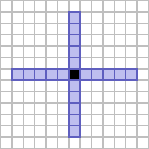
There are two immediately obvious ways in which the von Neumann neighbourhood can be extended to a range of 2:
- by counting all of the cells in the von Neumann neighbourhood of the cells which are in turn already in the von Neumann neighbourhood of a designated central cell, or
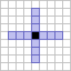
- by counting all of the cells which are at an orthogonal distance 1 or 2 from a central cell.
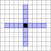
The former is usually referred to as the von Neumann neighbourhood of range 2, and gives a square shape which is rotated 45 degrees from its constituent cells. The latter is referred to as the cross neighbourhood of range 2,[1] giving a figure that resembles a plus shape.
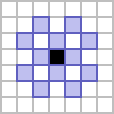
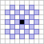
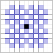
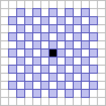
A third, more subtle way in which the range-1 von Neumann neighbourhood can be extended to higher ranges is by considering the grid to be a checkerboard, and only considering the squares of opposite parity to the center cell out to a distance of 2 both orthogonally and diagonally. The resulting neighbourhood is therefore referred to as the checkerboard neighbourhood of range 2.
These three methods can be used to generate neighbourhoods of any desired positive integer range, not just 1 or 2. Examples up to a range of 5 can be seen below.
| Range \ Type | von Neumann neighbourhood | cross neighbourhood | checkerboard neighbourhood |
|---|---|---|---|
| 1 | 
|

|

|
| 2 | 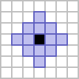
|

|
|
| 3 | 
|
|
|
| 4 | 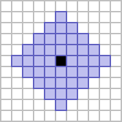
|
|
|
| 5 | 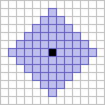
|
|
|
The Moore neighbourhood can also be generalized to higher ranges in much the same way. Two obvious examples follow:
- by counting all of the cells in the Moore neighbourhood of the cells which are in turn already in the Moore neighbourhood of a designated central cell, or
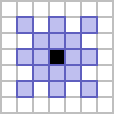
- by counting all of the cells which are at an orthogonal or diagonal distance 1 or 2 from a central cell.
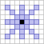
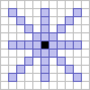
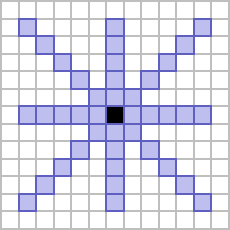
In these cases, the former neighbourhood is considered to be the Moore neighbourhood of range 2, whereas the latter is referred to as the star neighbourhood of range 2.[1] The former is a solid square, five cells to a side, and the latter generates a figure composed of a superimposed plus and X.
Both of these processes can again be used to create neighbourhoods of any desired range, with ranges up to 5 shown below.
| Range \ Type | Moore neighbourhood | star neighbourhood |
|---|---|---|
| 1 | 
|

|
| 2 | 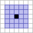
|
|
| 3 | 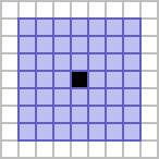
|
|
| 4 | 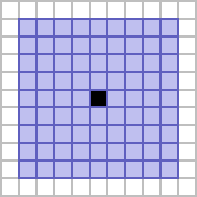
|
|
| 5 | 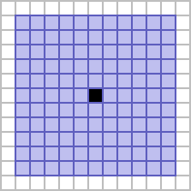
|
|
Symmetries
Static
Isotropic rules on the square tiling will always confirm to one of 16 different static symmetries. Its fourfold rotational and reflectional symmetry permits asymmetry, twofold cyclic symmetry, fourfold cyclic symmetry, twofold mirror symmetry, fourfold mirror symmetry and eightfold mirror symmetry, with further variants depending on the positioning of the center of rotation or the positioning and/or rotation of the planes of reflection.
| Asymmetry | Rotational symmetries | ||||
|---|---|---|---|---|---|
| Onefold | Twofold | Fourfold | |||
| Cell-centered | Edge-centered | Vertex-centered | Cell-centered | Vertex-centered | |
 C1 |
 C2_1 |
 C2_2 |
 C2_4 |
 C4_1 |
 C4_4 |
Kinetic
In addition to these 16 static symmetries, periodic patterns can also conform to one of 43 possible distinct kinetic symmetries. 16 of these duplicate the static symmetries above (but are notated differently in this context), whereas the other 27 arise for periodic patterns which have a mod unequal to their period.
Software support
As the square tiling is effectively the "default" grid for cellular automaton simulation, all general-purpose cellular automaton simulation programs support it.


